Lab 5
Pre-lab
By reading the datasheet for the motor driver, we see that we are supposed to hook up the red cable of the battery to Vin and the ground of the battery to GND. We also short the ground of the Artemis to the ground of the motor drivers. This common ground is important because we will be sending PWM signals from the Artemis to the motor controller so they need to have the same reference voltage. Each motor driver has two sets of inputs and two sets of outputs. We couple these in parallel so that we can provide a sufficient amount of current to make our robot fast. To parallel couple we short AIN1 and BIN1 and feed them a PWM signal, and we short AIN2 and BIN2 and feed them the other PWM signal. One PWM signal drives the motor in one direction while the other drives it in the other direction. We then short BOUT1 and AOUT1 together and BOUT2 and AOUT2 together and feed one of them to the black wire of one of the motors and the other to the red wire of the same motor. One chip controls one motor and each chip receives 2 PWM signals, one for each direction as previously mentioned.
Because of this, we need 4 PWM signals coming from the Artemis. I chose to send the PWM signals from pins 1, 3, 14, and 16 because these pins were all PWM enabled.
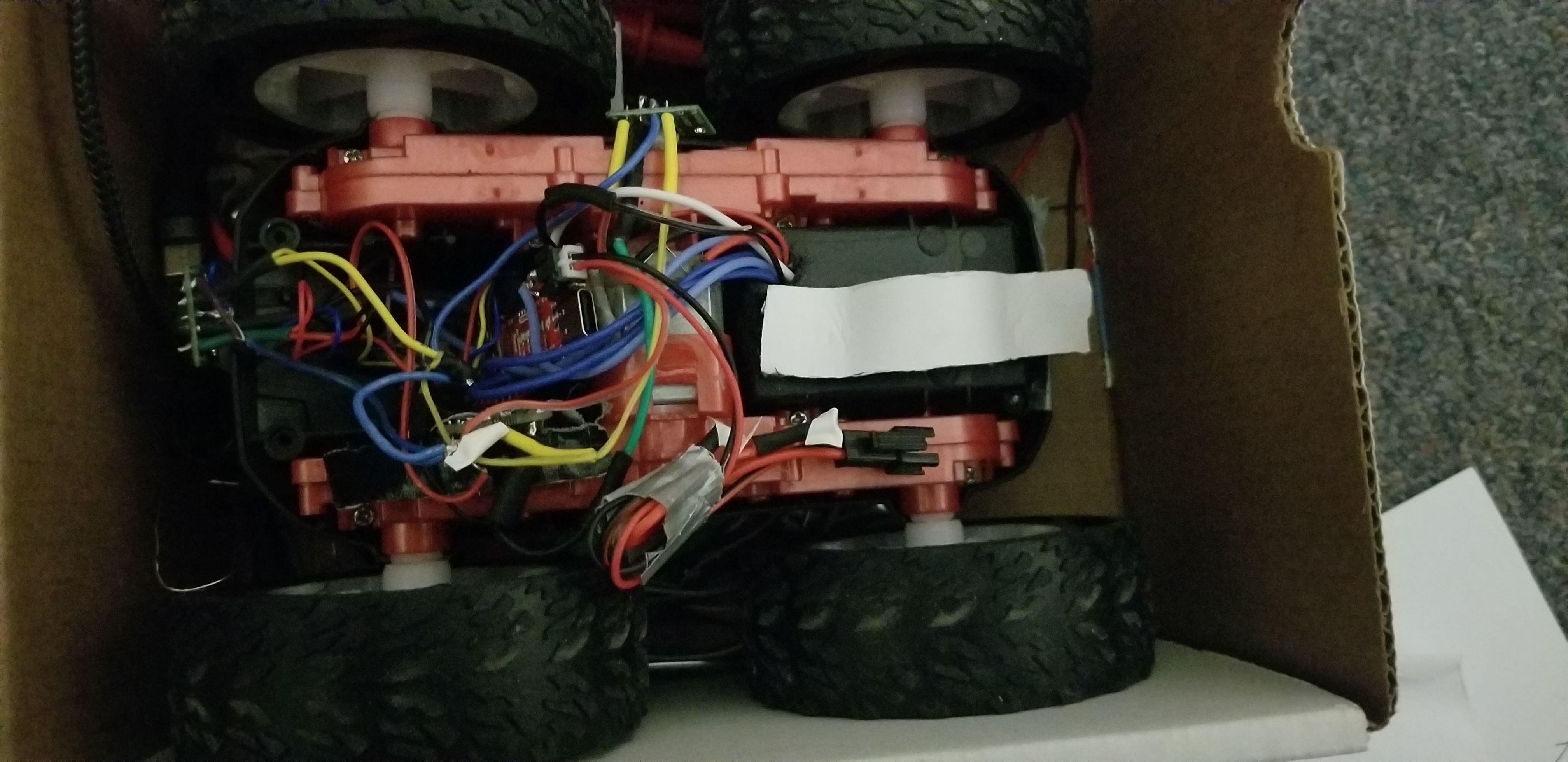
Below is a picture displaying how I hooked up my motor drivers to the Artemis and to the motors.
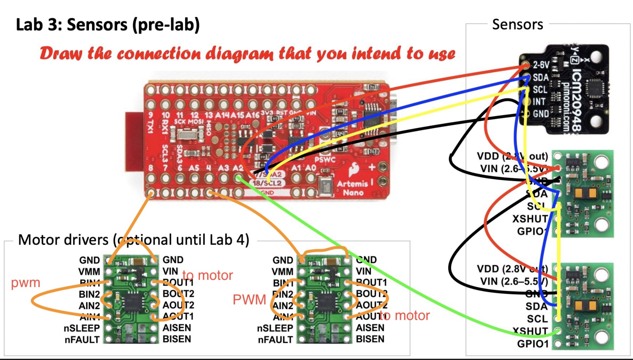
I put all of my motor drivers in the battery compartment and sealed it with duck tape hoping that I will rarely have to open it again for repairs. This will make fixing any of the wiring for the sensors much easier as I am not dealing with the clutter from the wires for the motor drivers. I stuck with the standard color coding of red being the positive terminal and black being ground. I made the PWM wires blue.
1.
Based on a discussion I had with one of the TA’s I soldered my motor drivers directly in the car and thus did not test them with an external power source. The Artemis Nano is a 3.3V device and thus when generating a PWM signal using the function generator to test the motors, 3.3V should be considered high. Additionally, the batteries we are using are 3.7V so it would make sense to set the external power source to 3.7V as well.
2.
To demonstrate control of the PWM I wrote the following and hooked up my car to the oscilloscope. This produced the results in the video below.
void setup() {
   pinMode(1,OUTPUT);
   analogWrite(1,50);
   delay(10000);
   analogWrite(1,100);
}
3.
The picture below shows I have successfully taken apart my car.
4.
Below you can see that I am successfully able to use analog write and a set of PWM signals to drive a motor in both directions.
To do this I wrote a simple script that sent a PWM signal along one of the lines to the motor driver, waited, and then zeroed the first PWM signal and sent another PWM signal along the other line to the same motor driver causing it to reverse its direction. As you can see in the video, the motors are also being powered by an external battery.
5.
I found that When a PWM signal of 30 out of 255 is given to the left and a pwm signal of 40 out of 255 is given to the right, the robot is just barely able to move itself. Left and right refer to the robot having the black side up and the side originally with the lights being designated as the front.
To make the robot go straight I used the following in setup
   pinMode(1,OUTPUT);
   pinMode(14,OUTPUT);
   analogWrite(14,40);//right
   analogWrite(1,65);//left
The results of this are shown below
The tape is 8ft long and the requirement was to go 6ft still over the tape.
The video below shows untethered open loop control of the robot. In the video, the robot goes approximately straight, turns left, turns back right, and then stops and spins in both directions.
I used the following code to accomplish this. As you can see each maneuver is executed for approximately 2 seconds.
void setup(){
//set up the pins
   //initialize it to go straight
   analogWrite(14,40);//right
   analogWrite(1,65);//left

}
//black side up and foward is side with lights
//16 and 14 are right 14 is forward 16 is backward
//1 and 3 are left


void loop() {
  long startTime=millis();
  long endTime;
  while(1){
    endTime=millis();
    if (endTime-startTime>10000){
      analogWrite(14,0);
      analogWrite(1,0);
      analogWrite(16,0);
      analogWrite(3,0);

    }
    if (endTime-startTime>2000 && endTime-startTime<4000){
      analogWrite(14,80);
      analogWrite(1,50);
    }
    if (endTime-startTime>4000 && endTime-startTime<6000){
      analogWrite(14,50);
      analogWrite(1,120);
    }
    if (endTime-startTime>6000 && endTime-startTime<8000){
      analogWrite(1,0);
      analogWrite(3,150);
      analogWrite(14,150);
    }
    if (endTime-startTime>8000 && endTime-startTime<10000){
      analogWrite(14,0);
      analogWrite(1,150);
      analogWrite(3,0);
      analogWrite(16,150);
    }
  }
I added the while(1) within the loop function so that I could capture startTime right before entering the infinite loop.
5960 Extra Questions
- The motors do not respond very quickly to changes in the signal. The analog write generates a PWM signal that acts as a sort of pseudo analog signal for the motor, and a higher frequency PWM signal is not going to provide any benefits as the steps are already unoticeable. The motor in a sense acts as a low pass filter.
- I discovered during this part of the lab that having delay() statements inside of a BLE portion of your program seems to break it. I suspected that there was some sort of timeout occuring so I came up with my own version of delay shown below where I use central.connected() to PING the other side of the BLE connection throughout the delay. This is shown below and seems to be a solution.
startTime=millis();
endTime=millis();
while(endTime-startTime<100cont){
  endTime=millis();
  int yes=central.connected();
  }
I used this delay to slowly ramp up the duty cylce of the PWM signal I was sending to the motor driver thus slowly ramping up the speed of the car. I used a for loop with a delay to more slowly ramp up and down the speed of the car. The for loop went from 0 to 255 and then was followed by another for loop that started at 255 and went back down to 0. The motor on one side of my car goes much faster than the other motor for a given PWM value and thus this caused my car to make a big circle as I was writing the same values to both motors drivers as they were ramped up.
After this I then did the motor ramp up, but at the same time it reported the values it was writing to the PWM lines to the Python script using a BLE notification. This was accomplished using the delay function detailed above. This is shown in a video below. Notice at the beginning that the notifications begin printing out as they are received.
Because of my intial issues with the BLE notification caused by the delay, Professor gave me a 2 day extension on this lab. I was not able to determine the max speed of the car because at this time, I do not feel comfortable driving it at full speed towards a wall in order to use the TOF sensors to calculate max speed.