Lab 12
Simulation
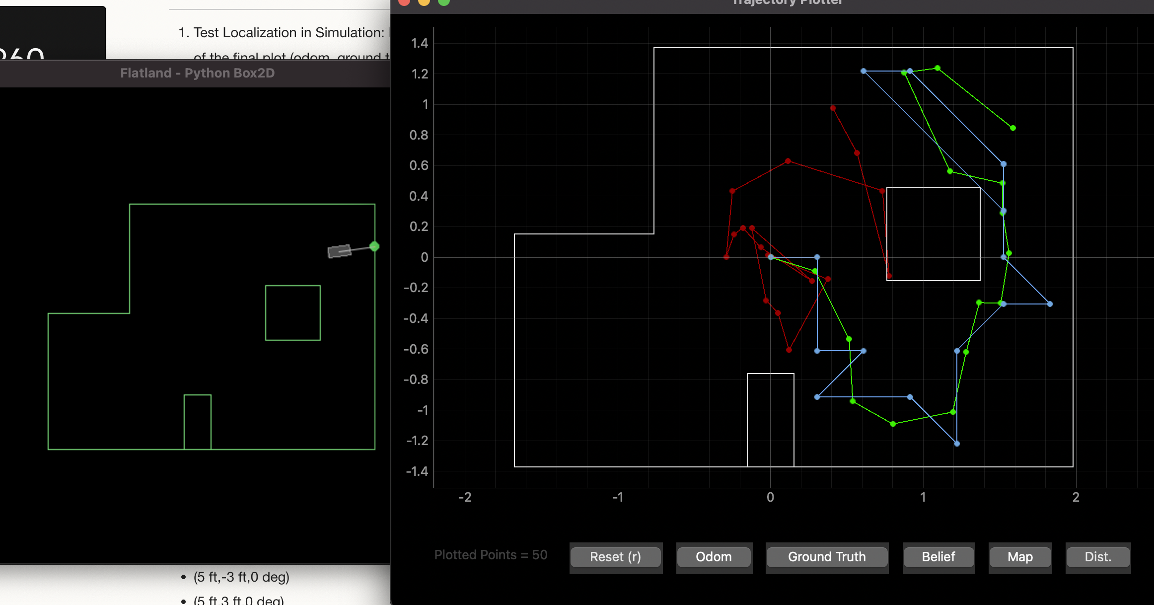
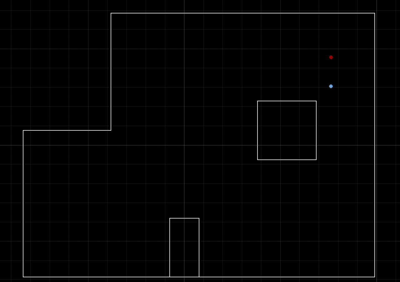
I ran the simulator as instructed. The result is shown below.
Real
Once I had run the simulation, I started working on real localization on my robot. To do this, I wrote code that instructed the robot to perform one turn and then to send over the TOF readings that it took along with the angle reading to the computer via bluetooth. This was very similar to the mapping lab, so I started with that as the base code. However, there was one major difference which was that the robot was only supposed to take 18 sensor readings over the course of the turn. To make this happen, I had the robot take a TOF reading every 20 degrees. Because of the way I did lab 9 it was much easier to do continuous rotation than to rotate 20 degrees, stop, take a reading, and repeat. Though this might be slightly less accurate because the robot is turning during its ToF reading, it was not worth the extra implement to change my previous implementation. My previous implementation (described in detail in the lab 9 write-up) was an integral controller which needs to build up the “juice” to turn when it is stopped, so stopping 18 times during a turn would not be ideal. I kept track of the angle and the last increment of 20 that I had completed and used this to take the measurements and end the turn when necessary. The following code accomplished this
startIntegral=micros();
angle+=abs(myBot.gX)*(float((startIntegral-endIntegral))/1000000);
endIntegral=micros();

if (measurement>=18) break;
if (angle-increment>=20){
  struct turn t;
  t.predictedAngle=angle;
  t.frontTOF=myBot.front;
  t.sideTOF=myBot.side;
  measurements[measurement]=t;
  measurement+=1;
  increment=angle;
}
In this code measurements holds the measurement information. As you can see every 20 degrees I set increment to angle and then keep integrating onto angle.
One down side of using the integral controller is that it sits for a while before it starts turning. When I integrate my angle I send the gyroscope value through an absolute value function meaning the angle always grows in the positive direction as it gets integrated. Because the robot sits for a while before turning while it integrates enough “juice” to start turning and the angle accumulates some error more quickly (due to sensor noise) than it would if I did not pass then gyro value through the absolute value function and there was some noise of opposite sign that would cancel itself out when integrating into the angle. Nonetheless, my solution worked well enough and I was able to get 18 sensor readings spaced approximately 20 degrees apart over the course of my turn.
Once I had these readings, I was able to send them into Python, convert them into a numpy column array, and feed them to the Python localization code to get an idea of where the robot was based on the sensor readings from the real robot. Getting the sensor readings into the numpy column array was done in the perform_observation_loop function which is shown below.
 def perform_observation_loop(self, rot_vel=120):
        global turnLog
        m=[]
        for i in turnLog:
            m.append(i[1]/1000) ###convert to meters
        m.reverse() #I turned clockwise
        print(m)
        measurements=np.array(m)[np.newaxis]
        return measurements.T, np.zeros((1,1),dtype=np.int8)
As the above code makes apparent, I receive the sensor readings into a global array called turnLog. Once the above function was implemented, and a few other small adjustments were made, I was localize with the sensor values from my robot. The video below shows the process. I send a command telling the robot to perform the turn, wait for it to finish, receive the sensor values, and do the localization.
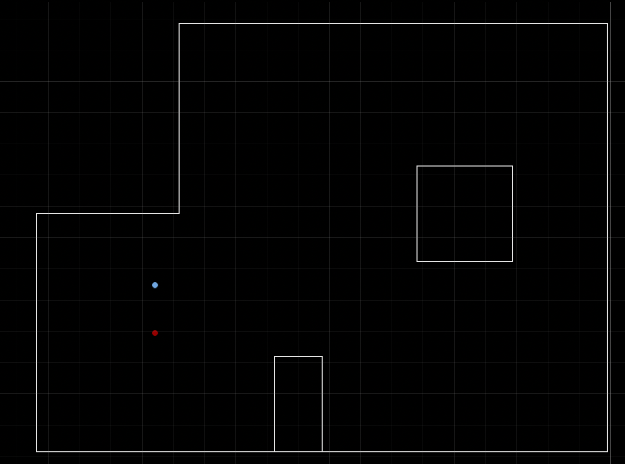
I did this for every point. The results at each point are shown below.
-3,-2
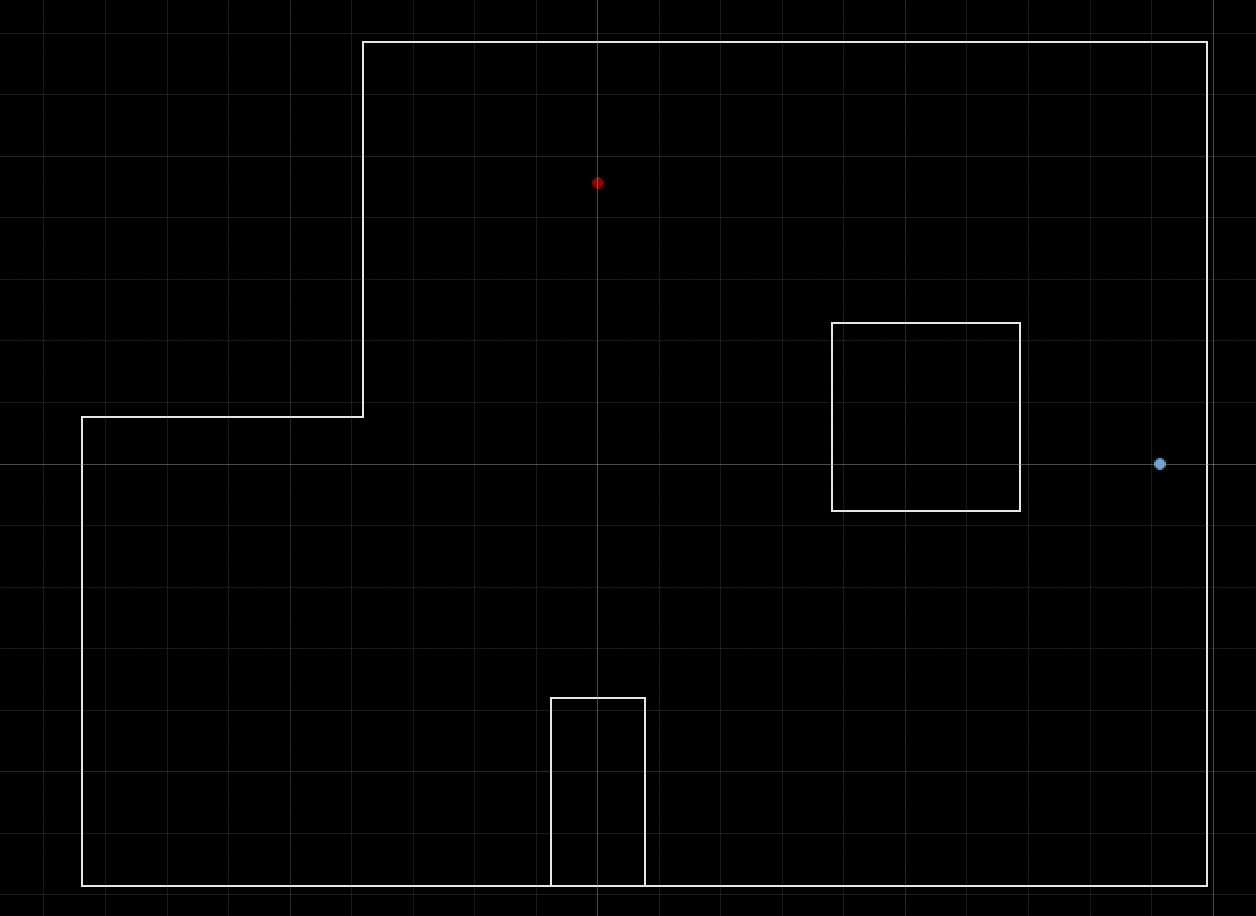
0,3
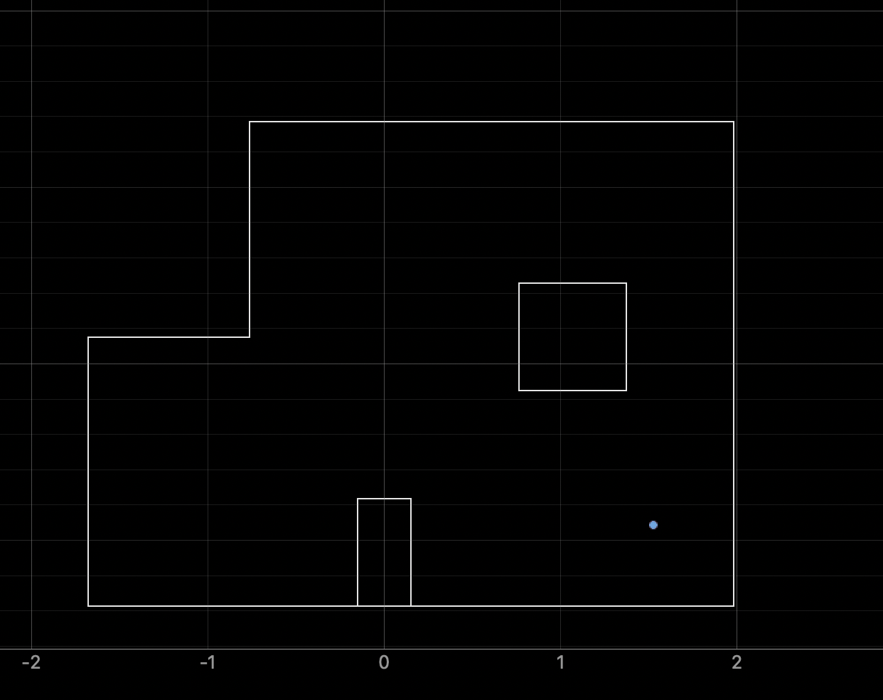
5,-3 (Perfect!)
5,3
As the images demonstrate the robot was able to localize (figure out where it was) pretty well at every point except for (0,3). In every other case the robot either predicted it was in the proper gird cell or thought that it was one cell away from where it actually was. However, in the case of (0,3) it was way off. There are a number of reasons why I think this might be the case. First, I think that my TOF sensor was not mounted directly perpendicular to the floor. This was not a problem for walls that were close away, but when the walls were far away, I think this could cause the sensor to either see over the wall or to see the floor. A good part of the scan at point (0,3) was trying to measure walls that were relatiely far away. This could have cause some bad sensor readings and thrown off my loclalzation. Additionally, looking at the map, it seems that point (0,3) is not an extremely unique position. In other words the correct scan would still produce results similar to that proper scans at other positions on the map.
Overall there was enough evidence to suggest that my basic robot localization was working. If I were going to alter my solution to try and get it to localize better at point (0,3), I would do a few things. First I would mount my sensor better so that it points directly forward. I would consider changing my sensor to long range mode. Additionally, I would get more accurate angle measurments by getting rid of the absolute value in the part of my code where I integrate the gyro values into the angle and adjust the rest of the signs accordingly. However, due to time, I need to move onto the next lab.